System emergency stop interface
The System emergency stop function can be used if the top module has its own Emergency stop circuit. Use this function to make it so both the robot and the top module are brought into Emergency stop when either system is triggered.
The interface has two inputs for bringing the robot into Emergency stop and two outputs for signaling when the robot is in Emergency stop.
The outputs are used to signal to the top module that the robot is in Emergency stop. When the robot is in an operational state, the outputs deliver 24 V. As soon as the robot enters Emergency stop, they deliver 0 V.
The inputs are intended to enable the top module to bring the robot into Emergency stop. When both inputs deliver 24 V, the robot can operate, but as soon as either or both of the inputs deliver 0 V, the robot enters Emergency stop.
If the input pins are unequally set for more than three seconds, the safety PLC registers this as an error in the system and needs to be reset before the robot can operate again. To do this, you must press the Restart button.
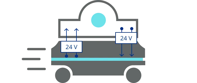
Not in Emergency stop
The robot is not in Emergency stop so the output is 24 V.
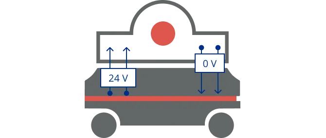
Robot and top module are in stationary states. Inputs are 0 V
The robot is in Emergency stop because it receives 0 V input from the System emergency stop interface
To see which pins in the electrical interface support this function, see Auxiliary Safety Functions A and B